Оа2КП * 6 – 20
ТУ У 31.3-00214534-036-2004 |
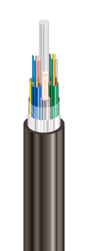
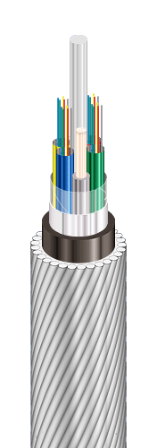
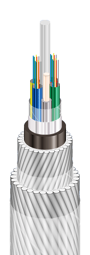
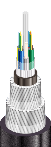
| Fiber optic module-core cables, double-layer galvanized steel-wire armoured, sealed with alumopolymer tape, with polyethylene outer sheath |
| Mark formation: |
| Оа2КП-[a]-[b] [c]6([d]x[e]+[f])-20 |
| [a] central strength element |
| • C – steel |
| • No marks – dielectric |
| [b] quantity of optical fibers in the cable, possible values |
| • 4, 6, 8, 10, 12, 14, 16, 20, 22, 24, 32, 36, 48, 78, 84, 90, 96 |
| [c] type of optical fiber |
| • E – single-mode (ITU-T G.652B) |
| • A – single-mode with extended wavelength band (ITU-T G.652D, ITU-T G.657A1) |
| • C – single-mode with non-zero shifted dispersion (ITU-T G.655) |
| • M – multimode with core and sheath diameter ratio 50 : 125 mm (ITU-T G.651) |
| • B – multimode with core and sheath diameter ratio 62.5 : 125 mm (IEC 60793-2) |
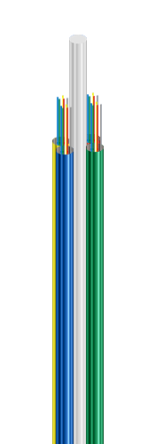
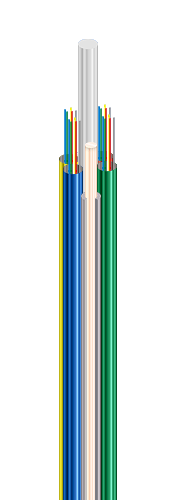
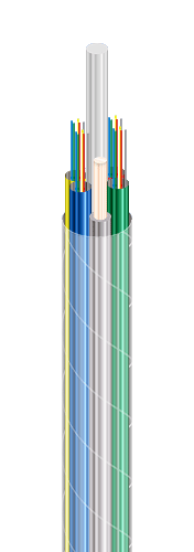
| [d] 2 ... 6 – number of optical modules in cable |
| [e] quantity of optical fibers in the module: |
| • 1 ... 16 |
| (f) quantity of insulated copper conductors in cable |
| Optical modules are completed with string fillers up to total number of core elements |
|
|
|
| Manufacturing of cables with two copper insulated remote power conductors instead of two string fillers is possible |
| Manufacturing of cables in climate version F is possible |
| Manufacturing of cables with steel strength element is possible |
| Manufacturing of cables with polyethylene intermediate sheath between armour layers is possible |
| It is possible to manufacture cables with gel-filled core or dry core (with water-blocking yarns and tapes) |
| It is possible to manufacture cables with a number of core elements up to and including 18 |
|
|
|
| Order placing: sample of indication (corresponds to configuration pattern) |
| Оа2КП-24A6(4x6+2)-20 • ТУ У 31.3-00214534-036-2004 |
|
|
|
| Cables are used for: |
| • laying in soils of all categories, areas with soils subjected to cryosolic distortions |
| • laying on the bottom of navigable rivers and deep water canals (depth up to 100 m) |